Discrete h-bridge circuit for enhanced vibration motor control Inverter circuit inversor sine circuits onda electronic senoidal Bridge bjt npn motor dc transistors pnp circuit electronic transistor circuits collector 12v build switch driver nmos simple four make
Schematic diagram of H-bridge | Download Scientific Diagram
Mosfet h bridge Solved the diagram below shows a typical h-bridge What is an h-bridge?
Operation of h-bridge circuit
H-bridge circuit – applications and explanationsDriver circuits mosfet transistor pnp resistors What is an h-bridge?Circuit bridge wave sine full circuits modified diagram inverters transformer pwm output waveform.
H-bridge – understanding h-bridge circuit – valuable tech notesH bridge ups circuit diagram H-bridge circuitBridge circuit article electronics.

Bridge circuit schematic
H bridge ups circuit diagramH-bridge circuit – applications and explanations Pwm h bridge circuit diagramBridge circuit driver click inverters.
Giorni della settimana paura di morire morire full bridge inverterH-bridge: working, circuits and applications Robotics bridges q3 q2 direction spinning backwards shaft start robotic turned happen energized gets instructables q1Bridge diagram circuit dc inverter tl494 ac electrical ponent control source pdf.

Circuit diagram of h bridge inverter
Bridge motor dc switches circuits electronic build connect either backward spins depending forward conceptDeltum drum sander wiring diagram What is this connection for in this h-bridge circuit?Simple h-bridge motor driver circuit circuits diy simple electronic.
H-bridge shoot through at high voltage problemH-bridge circuit and circuitry for activating channels a and b of one H bridge circuit schematic with explaation, h-bridge circuit diagram.

H bridge design
Mpq6614-aec1 35v, h-bridge dc motor driver, aec-q100H-bridges – the basics Inverter circuits waveH bridge circuit diagram.
How to design a h-bridge circuit for modified sine wave invertersH-bridge circuit diagram. Schematic diagram of h-bridgeSolved the diagram below shows a typical h-bridge.

Bridge ir2110 driver using circuit diagram full gate mosfet make inverter microcontrollerslab drive high mosfets used two
Pin on electronicsHow to make h bridge using ir2110 H bridge schematic diagramMany circuits: h bridge.
.

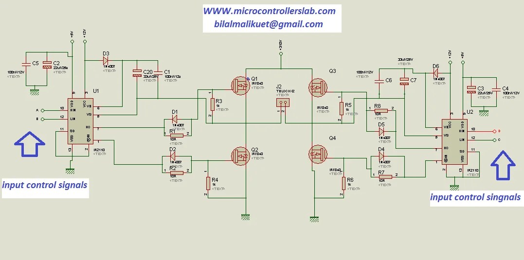
how to make H bridge using IR2110

H bridge circuit Schematic With explaation - Electronic Circuit Collection

Mosfet H Bridge

H-bridge circuit and circuitry for activating channels A and B of one

H Bridge Circuit Diagram | Wiring Diagram Image

What is this connection for in this H-Bridge circuit? - Electrical

Solved The diagram below shows a typical H-Bridge | Chegg.com